
Block diagrams can be difficult to read when you are unfamiliar with them. But there are a limited number of block diagrams to be encountered often. This page explains common block diagrams and how to read them.
Note: If you have not learned the basics of block diagrams, please read this page first.

- Block diagrams are easy to read if you remember common patterns.
- If a block diagram is very complicated, you can skip it for the moment.
- Simplify blocks as needed to represent the entire system concisely.
Feedback Control System
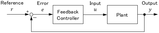
This is a quite basic block diagram. To determine the input $u$, the output $y$ is fed back, and the error $e$ is derived.
Feedforward Control System
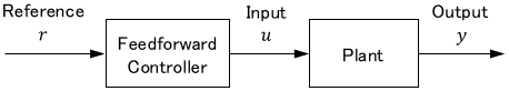
This is also a basic block diagram. To get the output $y$ as intended, the control input $u$ is determined by back-calculating the mathematical model of the plant.
For example, if we simply aim for $y=r$, the diagram looks like this:
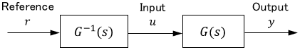
$G(s)$ is the transfer function of the system, and $G^{-1}(s)=\frac{1}{G(s)}$ is the inverse of it.
Note: For more details on feedback and feedforward control, please see this page:

Feedback & Feedforward Control System
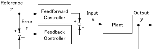
Here is an example of a block diagram combining feedback and feedforward control.
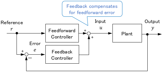
The upper half of the block diagram is for feedforward control, and the lower half represents a feedback control. The control method for the configuration shown above is also called Two-Degree-of-Freedom control.
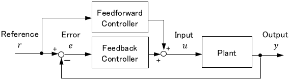
The following block diagrams are the same. It is just that the placement of the arrows can change the appearance quite a bit.
Cascade Control System
A cascade control system is a system in which another feedback control is included in the feedback control system. It may look complicated, but it is a simple system.
Let’s take an example. Assume we want to control a robot driven by a motor. In this case, the block diagram is as follows:
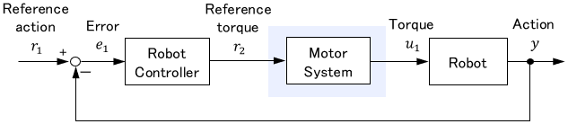
First, the robot controller derives the torque $r_2$ required to move the robot. Since the robot controller itself cannot generate torque, it passes the torque information to the motor system as the target torque. Upon receiving the target torque, the motor system generates torque and inputs it to the robot, which then moves.
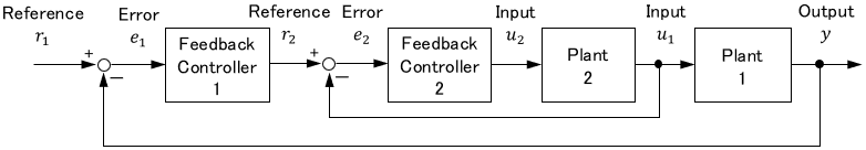
If the motor system is also driven by feedback control, it can be expanded as shown below. This is the cascade control system.
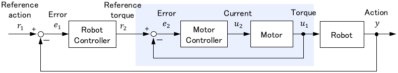
As in this example, the system is cascaded when the lower system is feedback-controlled to move the upper system.
Since each control is independent, it will be easier to understand if you mark the lower system blocks, as shown in the figure above.
Low-Pass Filter
Sometimes a transfer function pops up in a block diagram without explanation.
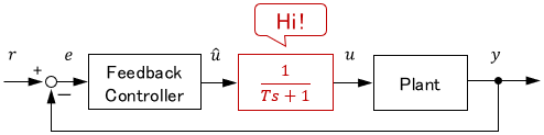
What’s this?! Did I miss something about a part of the system?
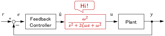
Of course, that is possible, and you should check carefully. But if the transfer function is a simple first- or second-order equation, it is often a filter.
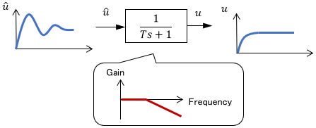
A first-order or second-order system can be used as a low-pass filter to cut high-frequency signals. For example, it can be inserted to suppress signal oscillations handily.
These filters may be implemented as hardware (e.g., an electric circuit), or as software (e.g., a digital filter in a program.)
So, strictly speaking, they are part of the controller but are separated to distinguish them from the essential parts. (In many cases, the filter is attached anyway as a stopgap measure).
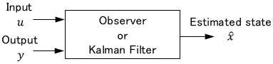
Observer and Kalman Filter
Observers and Kalman filters are systems that estimate states that cannot be obtained directly, using the outputs and system model as clues. They can be represented by a block diagram as follows:
This enables pseudo-feedback of states that cannot be obtained directly, as shown below:
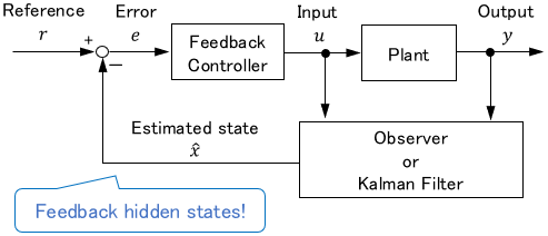
First, in the block, the output against the current input $u$ is predicted using the system model. Next, the prediction is compared with the actual output $y$ to derive a reasonable estimate $\hat{x}$.
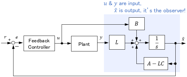
The observer sometimes appears as an expanded, complex block diagram, like the one below. But if you put together the part where the input $u$ and output $y$ enter and the estimated state $\hat{x}$ comes out, it becomes easy to read. (The same applies to the Kalman filter.)
Other Complex Block Diagrams
When you look at engineering books and papers, you sometimes encounter complicated block diagrams.
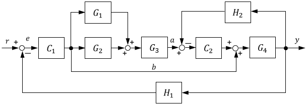
Can control experts understand this immediately?!
Rest assured that they don’t. You can skip over such difficult block diagrams for the moment.
Such block diagrams are to deepen your understanding visually after you have learned theories. So, first, check the theory with mathematical formulas.
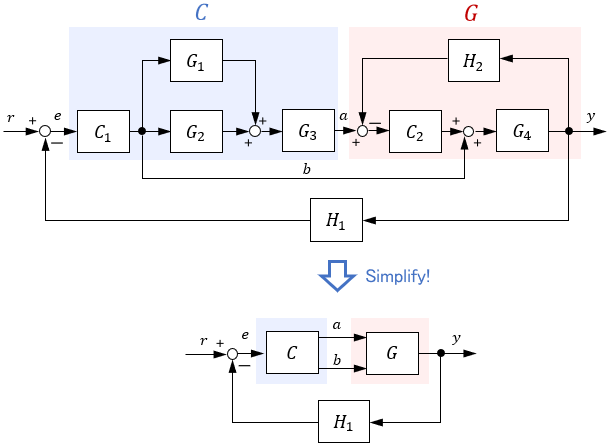
Block diagrams can be simplified
In most cases, block diagrams are used to represent system configurations intuitively. In such cases, it is better to simplify complicated blocks to express the entire system concisely.
For example, the complex block diagram shown earlier could be simplified as shown below if you just want to generally explain the entire system to others.
This page explained common block diagrams and how to read them. To conclude, a summary is shown here.
- Block diagrams are easy to read if you remember common patterns.
- If a block diagram is very complicated, you can skip it for the moment.
- Simplify blocks as needed to represent the entire system concisely.
Comments